Choosing a COB Graphic LCD is not just a matter of finding the sharpest screen. It means matching the display to its real job: a handheld meter, a wall-mounted controller, or a device used under bright factory lights. Resolution, viewing angle, interface, temperature range, power draw, and lifecycle all matter. One overlooked detail can force a costly redesign.
The wider LCD market offers useful context, but it does not measure COB graphic modules alone. Grand View Research estimated the global LCD market at USD 130.5 billion in 2024 and projected growth through 2030. Treat that figure as a broad industry indicator, not a forecast for COB modules. For a project, request the module’s datasheet and verify the viewing area, controller, operating temperature, and backlight current. Numbers on a product page are only a starting point.
Display analyst David Hsieh of Omdia has analyzed how display markets respond to application needs and supply conditions. A practical takeaway from that work—not a verbatim quotation—is: “Choose for the use case, not the headline specification.” A small screen may look clear on a desk yet wash out beside a sunlit window. Test it in the actual enclosure. Check the connector, too. This guide explains how to compare COB Graphic LCD options, ask suppliers better questions, and avoid choices that look right on paper but disappoint in the field. Some trade-offs remain; no single module fits every project.
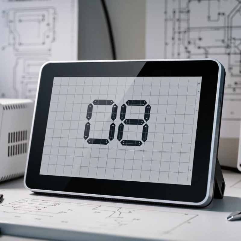
A COB graphic LCD uses a controller or driver IC mounted directly on a printed circuit board. The glass panel displays pixels arranged in rows and columns, while conductive connections carry signals between the board and the glass. In many modules, a flexible elastomeric strip joins these parts. The arrangement keeps the display compact and relatively easy to assemble.
The controller translates incoming commands into pixel patterns. Check its interface, supported resolution, and memory capacity against your project’s processor. A mismatch can mean extra circuitry or slower updates. The backlight matters, too. A small display may look clear indoors but fade beside a sunny window. Compare brightness, viewing angle, and operating temperature under realistic conditions. Details matter.
A common engineering trap is choosing by pixel count alone. A 128-by-64 display may still feel cramped if labels, icons, and readings compete for space. Sketch the actual screen before selecting the glass. Also verify connector pitch and mounting dimensions; a few millimeters can complicate a finished enclosure. Datasheets help, though some specifications leave room for interpretation. Ask for a sample when the viewing angle or contrast is critical, then test it with your own graphics and lighting.

Compare representative monochrome resolutions by their raw framebuffer requirement. Values assume one bit per pixel and are expressed in KiB (1 KiB = 1,024 bytes); controller overhead and additional buffers are not included. Higher resolutions provide more image detail but require more memory.
Start with the information the screen must show. A 128 × 64 display may suit simple menus, while charts or detailed icons need more pixels. Sketch the busiest screen and estimate how many characters or graphic elements must appear at once. Check the viewing distance, too. Text readable on a workbench may look cramped inside a handheld device. Measure the available panel area, including mounting space and cable clearance, before selecting a COB graphic LCD.
Next, consider where and how the display will operate. Bright ambient light can reduce readability, so compare contrast and backlight options under realistic conditions. A wide viewing angle may matter if users read the screen from the side. Confirm the controller interface, supply voltage, current draw, and temperature range against your system. These details are easy to overlook. A display can meet the resolution target and still create integration problems. Some requirements may change after a physical prototype; that is normal, but document the trade-offs rather than guessing.
Tips: Test sample text and graphics at the intended viewing distance. Check the display in both bright and dim conditions. Leave room for wiring and mounting tolerances. If power or readability remains uncertain, measure before finalizing the design.
A COB graphic LCD should be chosen around the information users must read, not the largest resolution available. A 128 × 64 display provides 8,192 addressable pixels; that may suit menus, icons, and short labels. Sketch the smallest text at its real viewing distance before selecting a module. Check the controller’s memory map and interface, too. Serial links use fewer host pins, while parallel interfaces can support faster updates, depending on the controller and timing. A pin-count win can still become a software headache.
Power figures need context. Compare logic and backlight current at the same supply voltage and brightness setting; otherwise, datasheet values can mislead. Backlight dimming may reduce consumption, but it also changes readability in bright rooms. For viewing characteristics, compare contrast and viewing-angle measurements under consistent conditions. IEC 61747-30-1 provides methods for measuring LCD optical characteristics, while VESA’s Flat Panel Display Measurements Standard offers a common framework for display measurements. Ask for the measurement conditions, not just a headline viewing angle. Then test the module on your actual enclosure: a slight tilt or a reflective window can make a good specification feel wrong. I would leave margin for that.
Choosing a COB graphic LCD starts with the space it must occupy. Measure the visible area, bezel opening, overall module size, and mounting-hole locations. Check connector position and cable bend radius too; a display may fit the panel but collide with a nearby board. Drawings can mislead. Compare the mechanical drawing with a physical sample, especially when the enclosure has tight tolerances.
Next, match the display to its operating environment. Check the specified temperature range, viewing angle, backlight brightness, and expected service hours. Sunlight near a window can wash out a screen that looks clear on a workbench. Heat changes things. A backlight driven continuously may age faster than one used intermittently, so avoid choosing brightness by appearance alone. If conditions vary, test the display in a representative enclosure.
Integration details can save time later. Confirm the interface, supply voltage, pin assignment, initialization sequence, and controller compatibility before fixing the design. Leave room for the connector and access to any adjustment components. Check whether the graphics library supports the required resolution and fonts; a technically compatible display can still demand awkward software changes. One detail is easy to miss: confirm that the viewing direction suits the final mounting angle. Then test the actual display with the intended cable, power source, and enclosure. A small mismatch may be manageable, but it should be found before production.
| Selection Dimension | What to Check | Realistic Reference Data | Integration Action |
|---|---|---|---|
| Module dimensions | Overall PCB size, thickness, mounting holes, and connector clearance. | COB graphic LCD modules are available in many outlines; dimensions are model-specific and should be taken from the mechanical drawing rather than inferred from resolution. | Compare the complete outline drawing with the enclosure, standoffs, fasteners, and nearby components. Include cable and connector bend space. |
| Viewing area and active area | Visible window size, active display area, and bezel overlap. | The active area is smaller than or equal to the visible viewing area. For example, a 128 × 64-pixel display has 8,192 addressable pixels, but its physical active-area dimensions depend on pixel pitch. | Align the enclosure window to the specified viewing area and check that the bezel does not obscure the active area. |
| Resolution and graphics | Pixel resolution, required text size, icons, and image detail. | Common graphic formats include 128 × 64, 240 × 128, and 320 × 240 pixels. Higher resolution generally requires more display memory and host-side data handling. | Mock up the actual interface at the intended pixel resolution. Confirm that fonts and symbols remain legible at the installed viewing distance. |
| Viewing direction | Viewing angle, display orientation, and whether the user looks above or below the module. | Viewing performance depends on the LCD mode and module construction. A specified viewing direction is not necessarily equally readable from every angle. | Test the display in its final orientation and enclosure under the expected user positions and ambient lighting. |
| Operating temperature | Required operating and storage temperature ranges. | Graphic LCD modules are offered with different temperature grades; examples include operating ranges around 0 to +50 °C or -20 to +70 °C. These are product-specific, not universal COB LCD limits. | Choose a module whose rated operating range covers the measured internal product temperature, including startup and thermal extremes. |
| Supply voltage and logic levels | Module supply, controller logic voltage, and any required bias or contrast voltage. | Many modules use a 3.3 V or 5 V supply, but allowable voltage and input thresholds vary. Some designs generate LCD bias internally; others need an external or adjustable contrast supply. | Check every power and logic pin in the datasheet. Do not assume a 5 V-tolerant interface from a 5 V module supply. |
| Interface and controller | Supported bus, controller command set, and host peripheral availability. | Graphic LCD modules may use a parallel interface, such as 6800- or 8080-style timing, or a serial interface such as SPI. Supported options depend on the module and controller. | Confirm pin assignments, timing, initialization sequence, and driver compatibility with the selected microcontroller or processor. |
| Connector and PCB integration | Connector type, pin pitch, pin count, cable direction, and PCB mounting method. | Modules may use pin headers, solder pads, or flex connections; pitch and pinout are not standardized across all modules. | Verify the exact pinout and mating connector. Review soldering access, cable routing, and strain relief in the assembled product. |
| Backlight and power budget | Backlight type, brightness, current, and dimming method. | LED backlights can be a significant part of module power consumption. Current and brightness vary by display size and backlight configuration. | Budget backlight current separately from logic current. Confirm whether the module includes a current-limiting circuit or requires an external driver. |
| Contrast and adjustment | Contrast range, temperature-related visibility changes, and adjustment circuit. | LCD contrast can vary with temperature and viewing conditions. Some modules require a contrast adjustment input or a negative bias voltage. | Test contrast across the operating temperature range and provide the required adjustment circuit or accessible calibration method. |
| Assembly and reliability | Mounting support, vibration exposure, ESD handling, and production process. | COB construction places controller circuitry on the module PCB; the display and interconnect still require suitable mechanical support and careful handling. | Support the PCB near mounting points, avoid pressure on the display glass, and follow the module’s handling and assembly guidance. |
A supplier’s quote is only a starting point. Ask for the LCD’s full part specification, production location, standard lead time, minimum order quantity, and written change-notification process. Request confirmation that the glass, controller, backlight, and connector will remain available for your expected production period. Vague answers matter. The World Semiconductor Trade Statistics November 2024 forecast projected global semiconductor sales of about $627 billion in 2024 and $697 billion in 2025. This signals a growing chip market, not guaranteed availability for a particular LCD module.
Test samples in the conditions the product will face. Check viewing angle, contrast, character legibility, and backlight uniformity under actual ambient light. Measure the module and verify its pinout; a small connector mismatch can force a board redesign. A bright sample can feel convincing. It is not enough. Ask for several samples from different production lots, plus inspection criteria and traceability details. Then compare the sample against the approved specification, not memory. For long-running projects, discuss forecast sharing, safety stock, last-time-buy notice, and an approved second source. Suppliers may promise continuity, but ask what happens when a component changes. I would document that answer; it is easy to assume availability lasts longer than it does.